


抗反射 (AR) 鍍膜
雷射資源指南第11.3部份。
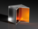
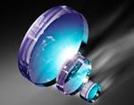
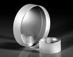
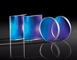
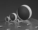
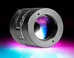
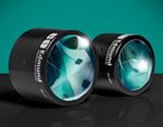
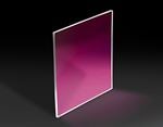
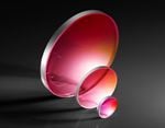
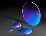
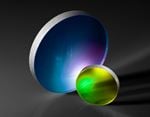
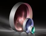
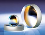
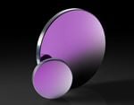
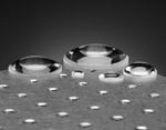
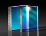
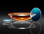
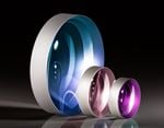
Edmund Optics offers all TECHSPEC® transmissive optics with a variety of anti-reflection (AR) coating options that vastly improve the efficiency of the optic by increasing transmission, enhancing contrast, and eliminating ghost images. Most AR coatings are also very durable, with resistance to both physical and environmental damage. For these reasons, the vast majority of transmissive optics include some form of anti-reflection coating. When specifying an AR coating to suit your specific application, you must first be fully aware of the full spectral range of your system. While an AR coating can significantly improve the performance of an optical system, using the coating at wavelengths outside the design wavelength range could potentially decrease the performance of the system.
Why Choose an Anti-Reflection Coating?
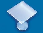
由於菲涅耳反射的緣故,光線由空氣通過未鍍膜玻璃基材時,每個介面約反射 4% 的光線,造成總共僅穿透 92% 的入射光,對雷射光學應用極為不利 (圖 1)。過多反射雷射光會減少光通量,可能造成雷射誘發損傷。抗反射 (AR) 鍍膜貼附在光學表面,以提升系統光通量,並減少反射向後穿透系統產生鬼影造成的各種危害。後向反射也會讓不需要的光線進入雷射腔,造成雷射系統不穩定。AR 鍍膜對含有多個穿透光學元件的系統而言特別重要。許多低光系統採用 AR 鍍膜光學元件,以便有效使用光線。

圖 1: 菲涅耳反射於每個材料介面產生。每個反射光每次抵達另一個介面時,部分反射光將遭受額外的菲涅耳反射1
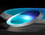
AR 鍍膜的設計,可讓薄膜上下邊界反射光束之間的相對相位偏移為180°。兩個反射光束之間會產生相消干涉,會在兩個光束離開表面之前將其抵消 (圖 2)。光學鍍膜的光學厚度必須為 $\tfrac{\lambda}{4}$, 倍數的奇數整數,其中 $ \small{\lambda} $ 為設計波長,或達到尖峰效能的最佳化波長,以便在反射光束之間達到所需的 $\tfrac{\lambda}{2}$ 路徑差,進而抵消光束。完整抵消反射光束所需的薄膜 折射率 $ \small{\left( n_f \right)} $ 可利用入射介質 $ \small{\left( n_0 \right)} $ 與基材 $ \small{\left( n_s \right)} $ 的反射率求得。

圖 2: 每個鍍膜層的折射指數及厚度都仔細控制,以便在每個反射光束之間形成相消干涉
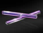
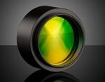
抗反射 V-coat 是一種 AR 鍍膜,可在以特定設計波長 (DWL) 為中心非常窄的波段中提升穿透效果。這種鍍膜類型稱為“V-coat”的原因,在於穿透與波長比對的曲線形成“V”字型,且其最小值位於DWL。V-coat 適合在使用單頻小線寬雷射,或窄半峰全寬 (FWHM) 光源時,獲得最大穿透效果。1 V-coats 反射率在 DWL一般低於 0.25%。不過鍍膜附近的反射曲線近乎橢圓形,而且反射率在 DWL 以外的波長大幅提升 (圖 3)。

圖 3:專為在 266nm 達到最高穿透的雷射 V-coat 範例
表 1 顯示愛特蒙特光學標準雷射 V-coat的反射率及保證雷射損傷閾值 (LIDT)。
| 標準雷射 V-COATS | ||
|---|---|---|
| DWL (nm) | 鍍膜規格 | 脈衝損傷閾值 $ \left( \tfrac{\text{J}}{\text{cm}^2} \right) $ |
| 266 | R <0.25% @ DWL | 3 @ 266nm, 20ns, 20Hz |
| 343 | R <0.25% @ DWL | 7.5 @ 343nm, 20ns, 20Hz |
| 355 | R <0.25% @ DWL | 7.5 @ 355nm, 20ns, 20Hz |
| 515 | R <0.25% @ DWL | 10 @ 515nm, 20ns, 20Hz |
| 532 | R <0.25% @ DWL | 10 @ 532nm, 20ns, 20Hz |
| 980 | R <0.25% @ DWL | 10 @ 980nm, 20ns, 20Hz |
| 1030 | R <0.25% @ DWL | 15 @ 1030nm, 20ns, 20Hz |
| 1064 | R <0.25% @ DWL | 15 @ 1064nm, 20ns, 20Hz |
表 1: 愛特蒙特光學標準雷射 V-coat 的反射率規格及保證雷射損傷閾值 - 可依要求提供自訂波長
由於光源波長越遠離 DWL,反射率就會急遽增加,因此採用 V-coat的光學元件,應於剛好或非常接近預定鍍膜 DWL 的情況下使用。Vcoat有一項有趣特性,就是其穿透曲線形狀為半週期性,也就是反射率在 DWL(例如 $ \tfrac{\lambda_0}{2} $ 或 $ \tfrac{\lambda_0}{4} $)4)諧波時達到局部最小值,而不像在DWL 時可達到最佳反射率。V-coat 通常僅由兩個鍍膜層組成。簡單的V-coat 可由厚度 $ \tfrac{\lambda}{4} $ 的單層組成,不過如果需要調整頻寬,或是沒有適當折射指數的鍍膜材料,就可能需要更多層。多層鍍膜也可能補償不同入射角,不過更為複雜,需要更大頻寬。如果 V-coat 層厚度不正確,鍍膜反射率就會增加,DWL 則會改變。愛特蒙特光學的 V-coat一般可達到遠低於 <0.25% 的最小反射率,但所有標準 V-coat 在 DWL都具有 0.25 以下的指定反射率。這樣可讓 DWL 少量偏移鍍膜容差。
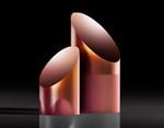
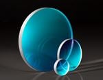
寬頻抗反射 (BBAR) 鍍膜可在更廣泛的波段提升穿透效果,普遍搭配使用寬光譜光源,以及可產生多種諧波的雷射。 BBAR 鍍膜的反射率值一般不像 V-coat 那麼低,不過穿透頻帶更寬廣,因此用途更廣。AR 鍍膜除了可應用於透鏡與窗鏡等穿透光學元件以外,也可用於雷射晶體及非線性晶體,以盡可能減少反射,因為空氣和晶體接觸之處會產生菲涅耳反射。1
寬頻抗反射 (BBAR) 鍍膜
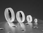
Edmund Optics offers all TECHSPEC® lenses with an optional single-layer, dielectric anti-reflection (AR) coating to reduce surface reflections. In addition, custom single-layer, multi-layer, V, and 2V coatings are available for both our off-the-shelf and large volume custom orders. View Custom Optical Lens Coatings for information.

圖 4: Wavelength selection chart
$\tfrac{\lambda}{4}$ MgF2: The simplest AR coating used is $ \tfrac{\lambda}{4} $ MgF2 centered at 550nm (with an index of refraction of 1.38 at 550nm). MgF2 coating is ideal for broadband use though it gives varied results depending upon the glass type involved.
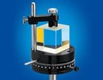
VIS 0° and VIS 45°: VIS 0° (for 0° angle of incidence) and VIS 45° (for 45° angle of incidence) provide optimized transmission for 425 – 675nm, reducing average reflection to 0.4% and 0.75% respectively. VIS 0° AR coating is preferred over MgF2 for visible applications.
VIS-NIR: Our visible/near-infrared broadband anti-reflection coating is specially optimized to yield maximum transmission (>99%) in the near-infrared.
Telecom-NIR: Our telecom/near-infrared is a specialized broadband AR coating for popular telecommunications wavelengths from 1200 – 1600nm.
UV-AR and UV-VIS: Ultraviolet coatings are applied to our UV fused silica lenses and UV fused silica windows to increase their coating performance in the ultraviolet region.
NIR I and NIR II: Our near-infrared I and near-infrared II broadband AR coatings offer exceptional performance in near-infrared wavelengths of common fiber optics, laser diode modules, and LED lights.
SWIR: Shortwave infrared broadband AR coating for applications from 900 - 1700nm.
圖 5, 圖 6, and Table 2 show EO’s standard BBAR coating options.

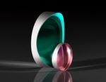
圖 5: 適用於可見光光譜的愛特蒙特光學標準 AR 鍍膜

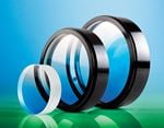
圖 6: 適用於近紅外線 (NIR) 光譜的愛特蒙特光學標準 AR 鍍膜,涵蓋 400 - 1600nm,不過可設計超過 2μm 的自訂鍍膜

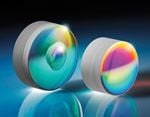
圖 7: EO’s standard AR coatings for the infrared (IR) spectrum
| 標準寬頻抗反射鍍膜 | ||
|---|---|---|
| 鍍膜說明 | 規格 | Coating Curves |
| λ/4 MgF2 @ 550nm | Ravg ≤ 1.75% @ 400 - 700nm | Download Curve |
| UV-AR [250-425nm] | Rabs ≤ 1.0% @ 250 - 425nm< | Download Curve |
| Ravg ≤ 0.75% @ 250 - 425nm | ||
| Ravg ≤ 0.5% @ 370 - 420nm | ||
| Laser UV-VIS [250-532nm] | Rabs≤1.0% @ 250 - 532nm | Download Curve |
| UV-VIS [250-700nm] | Ravg≤0.75% @ 350 - 450nm | Download Curve |
| Ravg≤0.5% @ 250 - 700nm | ||
| VIS-EXT [350-700nm] | Ravg ≤ 0.5% @ 350 - 700nm | Download Curve |
| VIS-EXT+ [350-700nm] | Rabs <1.5% @ 350 - 700nm @ ±30° AOI | Download Curve |
| Ravg <0.5% @ 350 - 700nm @ ±30° AOI | ||
| VIS-NIR [400-1000nm] | Rabs ≤ 0.25% @ 880nm | Download Curve |
| Ravg ≤ 1.25% @ 400 - 870nm | ||
| Ravg ≤ 1.25% @ 890 - 1000nm | ||
| Laser VIS-NIR [500-1090nm] | Ravg ≤ 1.0% @ 500 - 1090nm | Download Curve |
| VIS 0° [425-675nm] | Ravg ≤ 0.4% @ 425 - 675nm | Download Curve |
| YAG-BBAR [500-1100nm] | Rabs ≤ 0.25% @ 532nm | Download Curve |
| Rabs ≤ 0.25% @ 1064nm | ||
| Ravg ≤ 1.0% @ 1100nm | ||
| NIR I [600-1050nm] | Ravg ≤ 0.5% @ 600 - 1050nm | Download Curve |
| NIR+ [600-1050nm] | Rabs <1.5% @ 600 - 1050nm @ ±30° AOI | Download Curve |
| Ravg <0.5% @ 600 - 1050nm @ ±30° AOI/td> | ||
| NIR II [750-1550nm] | Rabs ≤ 1.5% @ 750 - 800nm | Download Curve |
| Rabs ≤ 1.0% @ 800 - 1550nm | ||
| Ravg ≤ 0.7% @ 750 - 1550nm | ||
| SWIR [900-1700nm] | Ravg ≤ 1.0% @ 900 - 1700nm | Download Curve |
| Rabs ≤ 1.5% @ 900 - 1700nm | ||
| SWIR+ [900-1700nm] | Rabs <1% @ 900 - 1700nm @ ±30° AOI | Download Curve |
| Ravg <0.5% @ 900 - 1700nm @ ±30° AOI | ||
| Laser NIR [1030-1550nm] | Ravg ≤ 0.7% @ 1030 - 1550nm | Download Curve |
| 2μm BBAR [1900-2100nm] | Ravg ≤ 0.5% @ 1900 - 2100nm | Download Curve |
| Rabs ≤ 0.25% @ 1900 - 2100nm | ||
Table 2: 愛特蒙特光學標準 BBAR 鍍膜的反射率規格
相關產品


參考資料
- Paschotta, Rüdiger. Encyclopedia of Laser Physics and Technology, RP Photonics, October 2017, www.rp-photonics.com/encyclopedia.html
更多技術資源
- 光學鍍膜簡介
- 反射鏡金屬鍍膜
- 高反射率鍍膜
- 雷射光學實驗室:鍍膜視頻
- 瞭解及指定雷射元件的LIDT
- 改裝原廠光學鏡片竅門 #4:為原始鏡頭添加鍍膜視頻
- 硬質鍍膜的優點
- 用於雷射應用的高反射率反射鏡線上研討會
- 雷射光學實驗室簡介


or view regional numbers
QUOTE TOOL
enter stock numbers to begin
Copyright 2023, Edmund Optics Inc., 14F., No.83, Sec. 4, Wenxin Road, Beitun District , Taichung City 406, Taiwan (R.O.C.)
California Consumer Privacy Act (CCPA): Do Not Sell My Information