了解表面品質規格
雷射資源指南第9.1 及 9.2部份。
光學元件的表面品質,是對可能在製造和處理過程中產生的表面瑕疵進行評估,例如劃痕及斑點或疵點。表面品質對雷射應用的重要性更甚成像應用,因為表面瑕疵可能會造成雷射誘發損傷。相較於搭配使用可見光或紅外線系統的光學元件,搭配使用紫外線波長的光學元件需要更緊密的表面品質容差,因為較短波長會遭受更大量的散射。有多種標準用於指定表面品質,例如美國軍用效能規範MIL-PRF-13830B 及 ISO 10110。
美國標準 MIL-PRF-13830B
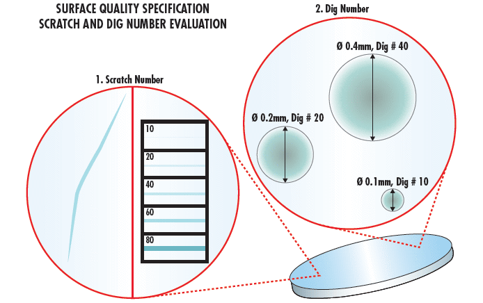
美國軍用效能規範 MIL-PRF-13830B 依據其中所述的校正標準,以“劃痕”數及其後接續的“疵點”數說明表面品質。1 劃痕數為下列其中一項任意數:10、20、40、60 、 80,其中劃痕亮度是由 10 增加至 80。以上數字並不是精確的量測結果,只是代表最符合元件劃痕亮度的校正標準劃痕亮度。檢測是在指定的暗場照明條件下進行;由於這是主觀視覺檢測,因此不同檢測人員之間的結果可能不同。不過疵點數是可量測的數量:最大元件疵點直徑,以 1/100 mm 為單位。例如元件若有直徑 0.4mm 的疵點,就會以疵點數 40 表示,若直徑為0.2mm 則疵點數為 20 (圖 1)。

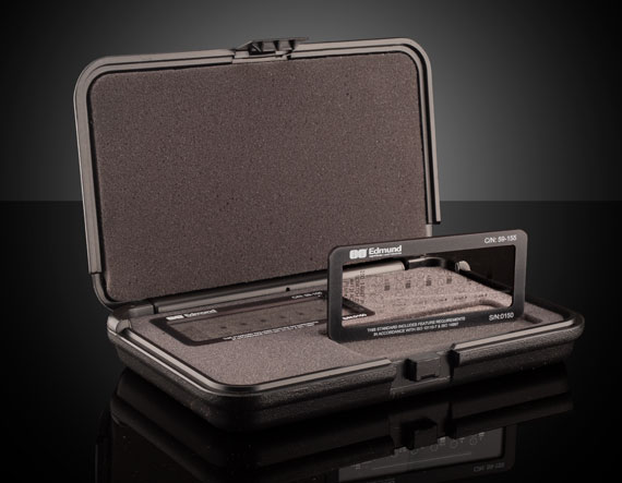
圖 1: MIL-PRF-13830B specifies that visual inspection be done using a 40W incandescent or 15W cool white fluorescent lamp
However, the dig number is a measurable quantity: the diameter of the largest component dig, given in 1/100 of millimeters. For example, a component with a 0.4mm diameter dig is represented with a dig number of 40 and one with a 0.2mm diameter with a dig number of 20 (圖 2).

圖 2: MIL-PRF-13830B 係依據校正標準目視比較劃痕及疵點,以描述光學元件表面品質特性
Once all scratches and digs have been quantified, determining the number of allowable defects is required. This number is determined as follows:
劃痕
If a maximum-sized allowable scratch is present on the optic, then the combined length of the maximum sized scratches $ \small{ \left( L_i \right)} $ may not exceed ¼ of the diameter of the optic $ \small{ \left( \phi \right) } $. For non-circular optics, the diameter of the circle with an area equal to that of the optic should be used.
疵點
Digs are pits in the surface of the optic, bubbles, or inclusions. The sum of the dig numbers $ \small{\left( N_i \right)} $ shall not exceed two times the maximum dig specification $ \small{\left( D \right) }$.
There shall be only one maximum sized dig per 20mm of diameter. Thus, if two maximum-sized digs are separated by less than 20mm, the part will not meet the specification. Additionally, all digs with a 10 specification shall be separated by at least 1mm. Digs less than 2.5µm in diameter should be ignored.
A laser optic with a 100mm diameter and specified surface quality of 10-5, based on the above limitations, can have several scratches with a brightness of 10 whose total length is not more than 25mm. It may not have more than 5 maximum-sized digs of 0.05mm (5 Dig Number), and the sum of the diameters of all digs must not exceed 0.5mm.
Scratch-dig specifications of 40-20 are widely considered standard quality for many optical applications. Precision laser applications typically require a scratch-dig of 20-10, whereas the most demanding laser applications, such as intra-cavity laser optics, usually require a scratch-dig of 10-5. Because the impact of surface imperfections on performance is wavelength dependent, UV laser applications often require a surface quality of 10-5, though a 10-5 optic used with a 10.6µm CO2 laser would be overspecified and unnecessarily expensive.
ISO 10110-7 第 7 篇:表面瑕疵
MIL-PRF-13830B的目視檢測既經濟又快速,不過其主觀性質欠缺精準度。ISO 10110-7 是更為量化的方式,依據特定零件區域表面瑕疵的實體大小及頻率指定表面品質。 (圖 3)雖然 ISO 10110-7 比 MIL-PRF-13830B 更精準,但也耗費更多時間及成本。

圖 3: While MIL-PRF-13830B only requires the visual inspection of an optic, ISO 10110-7 requires dimensional analysis using techniques such as differential interference contrast (DIC) microscopy
ISO 10110-7 並未區分劃痕及疵點,而是將兩者均視為表面瑕疵。2 10110-7 並未使用劃痕疵點數,而是提出允許瑕疵數 $ \left( \small{N_g} \right) $ 及等級數 $ \left( \small{A_g} \right) $ ,相當於區域瑕疵最大值的平方根 (圖 4)。

圖 4:ISO 10110-7 透過 $ \left( \small{N_g} \right) $ 限制允許瑕疵的數量,限制瑕疵大小上限的方式則是等級 $ \left( \small{A_g} \right) $
光學元件的 ISO 表面品質是以 5/ $ \small{N_g} $ x $ \small{A_g} $ 在圖上表示。 The total area obscured by imperfections is then given by:
ISO 10110-7 “尺寸”法透過 $ \small{N_g} $ 及 $ \small{A_g} $指定表面品質,不過 ISO 圖示也透過等同 MIL-PRF-13830B 的“視覺”法顯示表面品質。ISO 圖片的5/60-40,與 MIL-PRF-13830B 圖片的 60-40 意義相同。. The benefit of being able to indicate both “dimensional” and “visible” specifications is that it results in prints with all the standardization and lack of notes of an ISO print, with the ability to use the more convenient and cost-effective MIL-PRF-13830B surface quality standard for the majority of applications. The “dimensional” method can then be used for high-precision applications where surface quality is of the highest importance.
Learn About Other Optical Specifications and
Manufacturing Tolerances

Learn About Metrology at Edmund Optics®

參考資料
- U.S. Military Performance Specification. (1997). General specification governing the manufacturing, assembly, and inspection of Optical Components for Fire Control Instruments (Mil-PRF-13830B).
- International Organization for Standardization. (2017). Optics and photonics -- Preparation of drawings for optical elements and systems -- Part 7: Surface imperfections (ISO 10110-7:2017).


 上個章節
上個章節 


or view regional numbers
QUOTE TOOL
enter stock numbers to begin
Copyright 2023, Edmund Optics Inc., 14F., No.83, Sec. 4, Wenxin Road, Beitun District , Taichung City 406, Taiwan (R.O.C.)
California Consumer Privacy Act (CCPA): Do Not Sell My Information